16-1 REDUCTION GEARBOX

GEARBOX RENDERING
In this project, I was heavily involved in the development of a 16-1 colinear reduction ratio gearbox. There are two sets of gears each containing a 40 tooth and 10 tooth gear. The two sets of gears are rigidly connected which enables the 16-1 reduction ratio. The current view of the gear box is from the output-shaft.

GEARBOX MOTION STUDY
In this GIF you can see the original gearbox and how it was intended to operate. From this point, the gearbox went through multiple iterations including different gears, housing, and shaft
size.

FINAL GEARBOX DESIGN 3D PRINTED
In this image you can see the final version of the gearbox and the 3D printing time saving features. The final print took around three hours and the result was fantastic! Near the bottom of the gearbox you can see the initials of everyone involved with the project.
CNC MILLING MACHINE

FINAL CNC MILLING MACHINE RENDERING
In this image, you can see the final rendering of my team’s CNC milling machine. The machine utilizes ball screws and lead screws to operate, and it also has a plethora of custom-made parts.

LINEAR STAGE MOTION STUDY
In this GIF you can see the linear stages and how they were intended to operate. All linear stages of the CNC milling machine are roughly equivalent besides a few minor details.

LINEAR STAGE RENDERING
In this photo you can see a high-quality rendering of the linear stages. This particular rendering is the x-axis for the milling machine.
SCREWDRIVER

SCREWDRIVER EXPLODED VIEW RENDERING
In this project my team and I were tasked with reverse-engineering a screwdriver. We had to measure all of the small gears and design a CAD planetary gear system in solidworks. This photo is an exploded high-quality rendering of the screwdriver.
-2.png)
SCREWDRIVER DRAWINGS
In this project, I was heavily involved in the drawings for the 3D screwdriver. In this photo you can see all of the necessary views to recreate the screwdriver.
-1.png)
LOCK DRAWINGS
In this photo you can see the solidworks assembly and all the important views of the locking mechanism. This locking mechanism works by removing the ring gear of the planetary system, thus immobilizing the system.
CASTERS, JIGS, AND GRIPPERS
.png)
GRIPPER RENDERING
In this photo you can see a high-quality rendering of the robotic grippers. This particular rendering was used as the final design for the project.

JIG RENDERING
In this photo you can see a high-quality rendering of a jig used in the assembly of a wheel caster. This particular rendering was used as the final design for the project.

CASTER ASSEMBLY MOTION STUDY
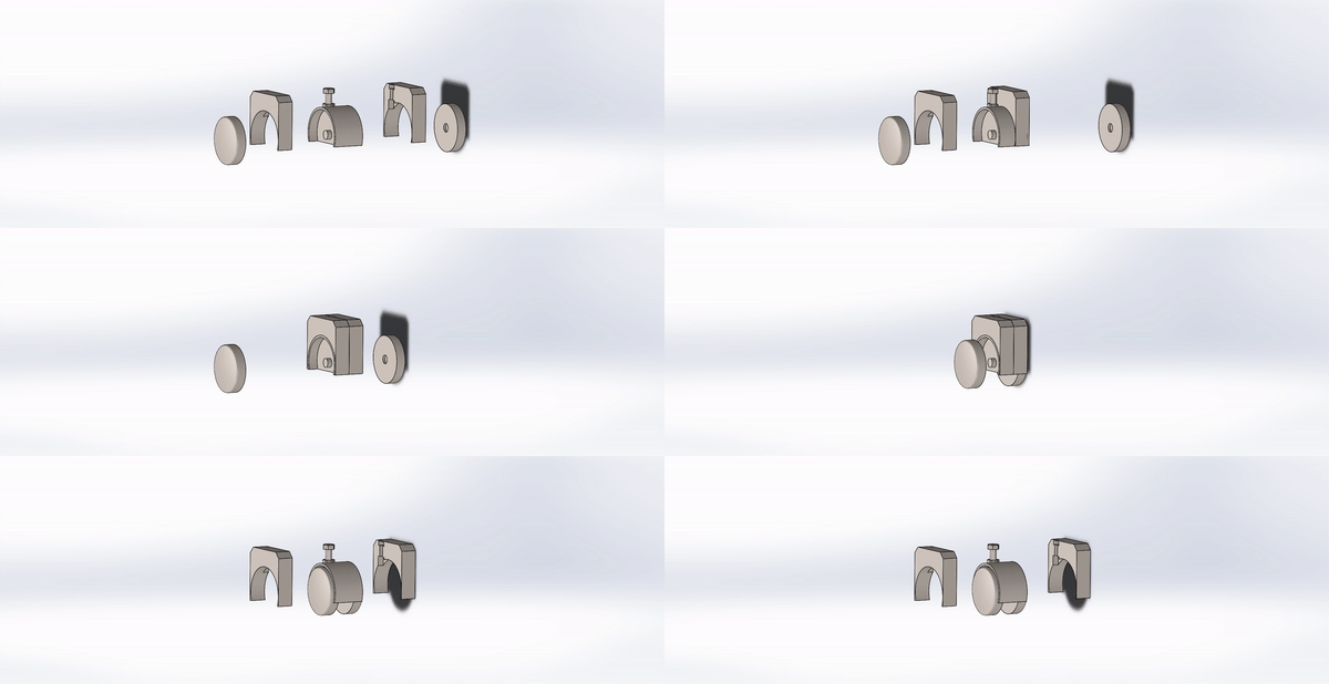
In this GIF you can see the final stages of the caster assembly and how the last fixture is intended to operate.
